UML Tutorials - Herong's Tutorial Examples - v1.05, by Herong Yang
State Machine Diagram - Transition Sequence Notations
This section describes the Transition Sequence Notation used in a UML State Machine Diagram. A Transition Sequence Notation presents a sequence of triggers and actions that make up a transition from one state to another.
A Transition Sequence Notation is the composite graphical notation used in a UML State Machine Diagram to represent a sequence of triggers and actions that make up a transition from one state to another.
A Transition Sequence Notation is drawn as a sequence of actions and control flows like a mini Activity Diagram with an incoming Transition Notation coming from the previous state and an outgoing transition pointing to the next state.
For example, the transition from "Idle" state to "Busy" state of an object may require a sequence of receiving an event, making a decision, sending a signal based on a condition, performing an action, etc. This sequence of actions can be drawn as a Transition Sequence Notation in a UML State Machine diagram as shown below:
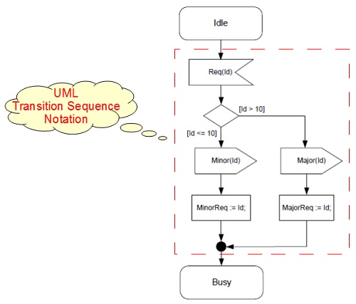
Note that the Action Notation in a transition sequence is drawn as a rectangle with straight corners, instead of strongly rounded corners as in an activity diagram.
Table of Contents
Introduction of UML (Unified Model Language)
UML Class Diagram and Notations
UML Activity Diagram and Notations
UML Sequence Diagram and Notations
►UML State Machine Diagram and Notations
What Is a State Machine Diagram?
State Machine Diagram - State Notation
State Machine Diagram - Pseudostate Notations
State Machine Diagram - Transition Notation
►State Machine Diagram - Transition Sequence Notations
UML Use Case Diagram and Notations
LibreOffice Drawing Extension - UML Elements