UML Tutorials - Herong's Tutorial Examples - v1.05, by Herong Yang
Activity Diagram - Control Flow Notation
This section describes the Control Flow Notation used in a UML Activity Diagram. A Control Flow Notation represents a transfer of execution control from one action to another action.
A Control Flow Notation is the graphical notation used in a UML Activity Diagram to represent a transfer of execution control from one action to another action.
A Control Flow Notation is drawn as a solid line with a line-arrow at one end pointing to the next action. For example, when the "Fill Order" action is ended, the execution control is transferred to the "Ship Order" action. This transfer of execution control is can be drawn as a Control Flow Notation in a UML activity diagram as shown below:
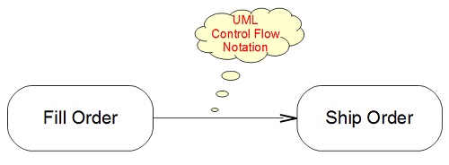
Table of Contents
Introduction of UML (Unified Model Language)
UML Class Diagram and Notations
►UML Activity Diagram and Notations
Activity Diagram - Action Notation
►Activity Diagram - Control Flow Notation
Activity Diagram - Start and Final Notations
Activity Diagram - Decision Notation
Activity Diagram - Merge Notation
Activity Diagram - Fork Notation
Activity Diagram - Join Notation
Activity Diagram - Object Notation
Activity Diagram - Send Signal Notation
Activity Diagram - Accept Event Notation
Activity Diagram - Partition (Swimlane) Notation
Activity Diagram - Frame Notation and Parameters
UML Sequence Diagram and Notations
UML State Machine Diagram and Notations
UML Use Case Diagram and Notations
LibreOffice Drawing Extension - UML Elements