UML Tutorials - Herong's Tutorial Examples - v1.05, by Herong Yang
State Machine Diagram - Pseudostate Notations
This section describes Pseudostate Notations used in a UML State Machine Diagram. Pseudostate Notations presents some logic nodes to build a complex transition from one state to another state.
Pseudostate Notations are graphical notations used in a UML State Machine Diagram to represent some logic notes to build a complex transition from one state to another state.
The following Pseudostate Notations are supported:
- Initial Pseudostate - Represents a logical point where initial actions are performed and ready to enter the default state. An Initial Pseudostate Notation is drawn as a small solid circle without outgoing transition pointing to the default state.
- Final Pseudostate - Represents a logical point where the modeled object stops functioning. A Final Pseudostate Notation is drawn as a small circle containing a smaller solid circle.
- Choice Pseudostate - Represents a decision point where a transition may change its direction based on certain conditions. A Choice Pseudostate Notation is drawn as a small diamond with one incoming transition and multiple outgoing transitions.
- Junction Pseudostate - Represents a merge point where multiple alternative transitions are coming to the same state. A Junction Pseudostate Notation is drawn as a small solid circle with multiple incoming transition and one outgoing transition.
- Fork Pseudostate - Represents a fork point where a transition is split into multiple concurrent transitions. A Fork Pseudostate Notation is drawn as a short solid line with one incoming transition and multiple outgoing transitions.
- Join Pseudostate - Represents a join point where multiple concurrent transitions are joined together to become one. A Join Pseudostate Notation is drawn as a small solid circle with multiple incoming transition and one outgoing transition.
The following picture shows some examples of Pseudostate Notations in a UML State Machine diagram:
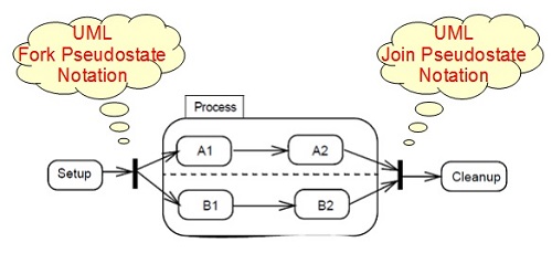
Table of Contents
Introduction of UML (Unified Model Language)
UML Class Diagram and Notations
UML Activity Diagram and Notations
UML Sequence Diagram and Notations
►UML State Machine Diagram and Notations
What Is a State Machine Diagram?
State Machine Diagram - State Notation
►State Machine Diagram - Pseudostate Notations
State Machine Diagram - Transition Notation
State Machine Diagram - Transition Sequence Notations
UML Use Case Diagram and Notations
LibreOffice Drawing Extension - UML Elements