UML Tutorials - Herong's Tutorial Examples - v1.05, by Herong Yang
Sequence Diagram - Lifeline Notation
This section describes the Lifeline Notation used in a UML Sequence Diagram. A Lifeline Notation presents an object that participate message interchanges with other objects.
A Lifeline Notation is the primary graphical notation used in a UML Sequence Diagram to represent an object which participates message interchanges with other objects.
A Lifeline Notation is drawn as a rectangle shape with a vertical dash line attached to it and the object name placed inside the rectangle. The vertical dash line is usually referred as the "lifeline" of the object. Communication messages are recorded sequentially downward along the "lifeline".
For example, the "Web Server" object is participating message interchanges with other others. This object can be drawn as a Lifeline Notation in a UML sequence diagram as shown below:
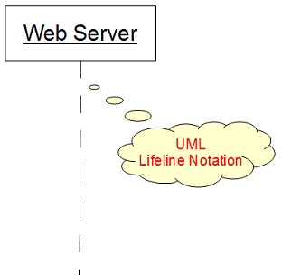
Table of Contents
Introduction of UML (Unified Model Language)
UML Class Diagram and Notations
UML Activity Diagram and Notations
►UML Sequence Diagram and Notations
►Sequence Diagram - Lifeline Notation
Sequence Diagram - Message Notation
Sequence Diagram - Execution Specification Notation
Sequence Diagram - Frame Notation
UML State Machine Diagram and Notations
UML Use Case Diagram and Notations
LibreOffice Drawing Extension - UML Elements